

Společnost SQN je považována za jednoho z vůdčích výrobců přenosných mixážních pultů pro filmovou a televizní výrobu. Mixážní pulty SQN jsou známé svou robustností, dlouhou životností a schopností pracovat v téměř jakýchkoliv podmínkách. Na výběr je ze dvou typů – čtyřkanálový a pětikanálový, které pokrývají celé spektrum uživatelských požadavků od základního ENG přes vícekamerová interview po filmovou produkci či nahrávání v exteriéru.
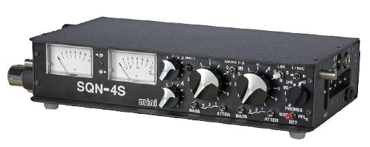
SQN-4S_mini mk II
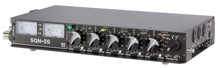
SQN-5S Series II


Parametry
| Mixer InputsCH1 & CH2 |
Transformerless balanced inputs using standard Cannon XLR-3F connectors.Each channel is switchable for:
|
| Sensitivity | -78dBu for nominal line level (PPM4, 0VU) with the channel gain at maximum and the master gain at 0dB |
| Max Level, Mic Inputs | -20dBu (+4dBu with full attenuation) |
| Line Level | Line Attenuation is 40dB before the mic preamp. |
| Noise Figure | -130dBu (A weighted) from a 200 Ohm source. |
| Mixer Inputs CH3 & CH4 | Transformerless balanced inputs using standard Cannon XLR-3F connectors.Each channel is switchable for:
|
| Sensitivity | -68dBu for nominal line level (PPM4, 0VU) with the channel gain at maximum and the master gain at 0dB |
| Max Level, Mic Inputs | -20dBu (+4dBu with full attenuation) |
| Line Level | Line Attenuation is 40dB before the mic preamp. |
| Noise Figure | -126dBu (A weighted) from a 200 Ohm source. |
| Frequency Response | 20Hz to 20kHz +0, -1dB, referred to 1kHz. |
| Crosstalk | Isolation, channel to unrelated channel: 75dB at 1kHz, 60dB at 15kHz. |
| Channel Configuration | The routing arrangements for CH1 & CH2 differ from those for CH3 & CH4. |
| Channels 1 & 2 [GANG 1-2] |
The operation of the CH1, CH2 pair is controlled by the GANG 1-2 switch on the front panel. This switch has three positions:
|
| Phase Switch | Channel 2 can have its phase inverted by means of a switch [INV2] on the right hand side panel. Note: this has the incidental effect of interchanging left and right in an MS encoded signal. |
| Channels 3 & 4 |
Each channel can be routed to LEFT, RIGHT or CENTRE. |
| Master Gain | The master gain control is located on the left hand side panel. It controls the level of all four channels. It is normally placed in its detented calibrated position and provides a reserve of 3dB extra gain above this setting. |
| Monitor Return Input | Balanced inputs with a range of sensitivity from -20dBu to +20dBu for loudness parity with the internal monitoring. The sensitivity is adjusted by a screwdriver preset on the left hand side panel. |
| Balanced Outputs | Two line driver amplifiers provide balanced outputs to the Main I/O Multi-way connector. |
| OutputAttenuators | The level at the Multi-way connector may be attenuated by 50dB to provide a nominally microphone level feed. |
| Line Drivers | Electronically balanced quasi-floating sources with a clipping level above +20dBm into 600 Ohms. Distortion at the nominal peak level of +8dBm is less than 0.01% with a 600 Ohm load 20Hz to 20kHz. The output resistance is 75 Ohms. The outputs may be connected to unbalanced loads if required. |
| Unbalanced Outputs |
|
| Meters | Twin peak reading, logarithmic level meters with Peak Programme Meter (PPM) dynamics. Meter Scaling may be BBC PPM, Nordic Norm, or SMPTE. VU meters can also be provided. The meters are normally calibrated with the mixer driving a bridging load of 10k Ohms. While the mixer is operating, the meters are illuminated by low power light emitting diodes. |
| Line Output Level | The nominal line level is normally set at 0dBu for PPM metered mixers and +4dBu for VU metered mixers. Peak level, which is used as a reference for the limiters, is considered to be 8dB above this setting. Other calibration levels are readily available to order. |
| Output Limiters | [O]ff [M]ono [S]tereo (ganged) Attack time constant 0.5ms, release time 100ms. The limiter range is 20dB. An LED for each output channel indicates limiter action. This Graph shows the entry into limiting on a steady signal for a nominal peak level of 8dBu |
| Line-up Tone | The Line-up tone is a sine wave at 1kHz with distortion below 0.1% which is inserted into both channels, displacing the audio output. When the [GANG 1-2] switch is in either of the ganged positions, the left hand channel tone is interrupted for 250ms every 3s. The tone switch on the front panel is a three position toggle, shared with the Slating Microphone. |
| Monitoring | Amplifiers with adjustable gain capable of driving most types of headphone to a suitable level. Headphones with a resistance of around 25 to 200 Ohms per side will make best use of battery power. Pre-Fade listening to input Channel 4 is possible. As MS matrixing of the two output channels is also possible, an MS recording may be monitored as the equivalent AB stereo. The headphone gain control is on the left hand side panel. Please note that with some headphones damage to the hearing may be possible if the phones gain is habitually set too high. |
| Monitoring Mode Selector |
The monitoring mode rotary selector switch on the front panel [PHONES] has the following functions.
|
| Monitoring Source Selector |
A front panel toggle switch selects the monitoring source as either internal [MXR] or external [RET] |
| Pre-Fade Listen | An extra position [PFL4] on the monitoring source selector switch selects Pre-Fade listen for channel 4. |
| Slating Microphone | A microphone is mounted behind the front panel near the centre of the mixer. When in use, the output of the microphone is levelled by a compressor and displaces the normal audio, appearing on the mixer outputs and in the monitoring system. While the microphone is active, the monitoring mode automatically reverts to the internal or [MXR] setting. The Slating Microphone switch on the front panel is a three position toggle, shared with the Line-up tone. |
| Batteries | Six AA size cells in a quick change compartment. The acceptable range of voltages is 5 to 18 Vdc allowing the use of most cell technologies. |
| Battery Test | The right channel meter is fitted with a suppressed-zero battery voltage scale, selected by a front panel push button. |
| External Power | A supply in the range 5 to 18 Vdc may be used. The maximum consumption will be 2.2 watts maximum. The power input terminals float with respect to ground. Either or neither side may be grounded at will, thereby allowing the use of floating supplies or grounded supplies of either polarity. There will be no possibility of hum-loops being formed. |
| Temperature Range | The mixer is designed to work over the temperature range of -20 to +60 °C. |
| Dimensions | The dimensions of the mixer case are: Height 44mm, Width 210mm, Depth 120mm |
| Weight | The weight of the mixer without batteries is 1.1kg |
Parametry
| Mixer Inputs | Five transformerless balanced inputs using XLR-3 type female connectors. Each channel is switchable for:
|
| Sensitivity | -78dBu for nominal line level (PPM4, 0VU) with the channel gain at maximum and the master gain at 0dB |
| Max Level, Mic Inputs | -20dBu (+4dBu with full attenuation) |
| Noise Figure | -130dBu (A weighted) from a 200 Ohm source. |
| Frequency Response | 20Hz to 20kHz +0, -1dB, referred to 1kHz. |
| Crosstalk | Isolation, channel to unrelated channel: 75dB at 1kHz, 60dB at 15kHz. |
| Channel Configuration | The mixer has five input channels, all of which have the same input selectors, bass cuts and attenuators. The routing arrangements for CH1 & 2 differ from those for CH3, 4 & 5. |
| Channels 1 & 2 [GANG 1-2] |
The operation of the CH1, CH2 pair is controlled by the GANG 1-2 switch on the front panel. This switch has three positions:
|
| Phase Switch | A front panel switch inverts CH2 phase. This also interchanges left and right in an MS encoded signal. |
| Channel 3 | CH3 can be routed to LEFT, RIGHT or to a PANpot. |
| Channels 4 & 5 | Each of CH4 and CH5 can be routed to LEFT, RIGHT or CENTRE (both). |
| Monitor Return Inputs | Two sets of monitor return inputs are provided EX1 on a combined 12-Way connector[A]: Balanced inputs with a range of sensitivity from -20dBu to +20dBu for loudness parity with the internal monitoring. EX2 on a 3.5mm jack [EX2]: Unbalanced inputs of similar sensitivity.The sensitivity is adjusted by a screwdriver preset on the base, with an internal range switch. |
| Mixing Bus Inputs | The SUBSIDIARY I/O connector [B] carries two inputs directly into the summing amplifiers. Sensitivity is 0dBu for +8dBu at the balanced outputs with the master gain set at 0 and can be trimmed internally. |
| Balanced Outputs | Two pairs of line drivers are provided. The No.1 outputs are available on a combined 12-Way connector [A] and the No.2 outputs on a 5-Way XLR connector. |
| Line Drivers | The line drivers are electronically balanced sources with a clipping level of +22dBm into 600 Ohms. Distortion at the nominal peak level of +8dBm is less than 0.01% with a 600 Ohm load 20Hz to 20kHz. Output resistance is below 10 Ohms and it is permissible to forcibly unbalance any of the outputs without it affecting the others. |
| Output Attenuators | Switches on the base allow attenuation by 50dB at either set of connectors for microphone level feed. |
| Unbalanced Outputs | Two stereo 3.5mm jacks, UB and UB2 carry 220 Ohm unbalanced outputs at 6dB below the main outputs, while the 3.5mm jack UBM carries Mic-Level signals at 50dB below the main outputs.The SUBSIDIARY I/O connector [B] shares the UB2 220 Ohm unbalanced output. |
| Direct Outputs, All Channels |
The SUBSIDIARY I/O connector [B] carries the five unbalanced, pre-fader mic preamp outputs at a nominal level of -10dBu peak from a 220 Ohm source resistance.If a link to ground is made on the connector, post-fader outputs are available instead. If a further link is made, CH4 and CH5 are removed from the mix and the signal routing for CH3 is changed so that selecting PAN for CH3 will switch the channel out of the mix.
A presettable line-up tone for aligning external recorders is provided, ganged with the main tone. Its level of -10dBu corresponds to the preamp output with the fader at 5 and peak level at the mixer output. The output level (and tone) may be attenuated by 6dB using internal switches. |
| Meters | Twin peak reading, logarithmic level meters with Peak Programme Meter (PPM) dynamics. Scaling may be BBC PPM, Nordic Norm, or SMPTE. VU meters can also be provided. The meters are normally calibrated with the mixer driving a bridging load of 10k Ohms. While the mixer is operating the meters are illuminated by low power light emitting diodes. |
| Line Output Level |
The nominal line level is normally set at 0dBu for PPM metered mixers and +4dBu for VU metered mixers. Peak level, which is used as a reference for the limiters, is considered to be 8dB above this setting. Other calibration levels are readily available to order. |
| Output Limiters | [O]ff [M]ono [S]tereo (ganged) Attack time constant 0.5ms, release time 100ms. The limiter range is 20dB. An LED for each output channel indicates limiter action. This Graph shows the entry into limiting on a steady signal for a nominal peak level of 8dBu |
| Line-up Tone | The Line-up tone is a sine wave at 1kHz with distortion below 0.1% which is inserted into both channels, displacing the audio output. When the [GANG 1-2] switch is in either of the ganged positions, the left hand channel tone is interrupted for 250ms every 3s. The tone switch on the front panel is a three position toggle, shared with the Slating Microphone. |
| Monitoring | The mixer has a pair of headphone amplifiers with adjustable gain. The outputs are available on both quarter inch and 3.5mm jacks and are capable of driving most types of headphone to a suitable level. Pre-Fade listening to four of the input channels is possible as is MS matrixing of the two output channels so that an MS recording may be monitored in the equivalent AB stereo. The headphone gain control is a tall knurled knob easily accessible at the front of the left side panel. |
| Monitoring Mode Selector |
The monitoring mode rotary selector switch on the front panel [PHONES] has the following functions.
|
| Monitoring Source Selector | A front panel toggle switch selects the monitoring source as either internal [MXR] or external [AUX] |
| Pre-Fade Listen | A pair of front panel toggle switches selects Pre-Fade Listen for channels 2 or 3 and 4 or 5. The switches are three position, centre off. |
| Slating Microphone | A microphone is mounted behind the front panel near the centre of the mixer. When in use, the output of the microphone is levelled by a compressor and displaces the normal audio, appearing on the mixer outputs and in the monitoring system. While the microphone is active, the monitoring mode automatically reverts to the internal or [MXR] setting. The Slating Microphone switch on the front panel is a three position toggle, shared with the Line-up tone. |
| Batteries | Eight AA size cells housed in a quick-change compartment. The acceptable range of voltages is 6 to 24 Vdc allowing the use of most cell technologies. |
| Battery Drain | 135mA at 12 Vdc with unpowered mics. Battery life with alkaline cells will be about 10 hours. |
| Battery Test | The right channel meter is fitted with a suppressed-zero battery voltage scale, brought into operation by a front panel push button. |
| External Power |
A supply in the range 6 to 24 Vdc may be used. The maximum consumption will be 2.5W and quiescent consumption, without microphones, 1.6W. The input terminals float with respect to ground. Either (or neither) side may be grounded at will, thereby allowing the use of floating supplies or grounded supplies of either polarity. There will be no possibility of hum-loops being formed. |
| Power Distribution | The mixer carries two four-way connectors, one of which [DC] gives access to the internal batteries for charging and also serves to connect to an external power source. The second connector [PT] is an output which provides a switched, short circuit proof connection to the power supplied to [DC]. This allows the mixer to be used as the focal point for a system of interconnected devices, all controlled from the mixer’s power switch. |
| Temperature Range | The mixer is designed to work over the temperature range of -20 to +60 °C. |
| Dimensions | The dimensions of the mixer case are: Height 47mm, Width 297mm, Depth 161mm |
| Construction | The outer case of the mixer is made of aluminium. The end blocks holding the connectors and the panpots are milled from solid aluminium bar. Inside the mixer is an inner compartment of steel, tin-plated after forming, which contains all of the circuitry that might be sensitive to radio frequency interference. The top and bottom of this compartment are sealed by copper screens and rf gasket material and all inputs to and outputs from this compartment are filtered. The circuitry is constructed on multi-layer printed circuit boards with internal ground and power planes which ensure the integrity of the internal grounding system.All control knobs are special to SQN and are turned and milled from solid aluminium bar. The internal battery compartment is milled and bored from a solid block of polyacetal engineering plastics material and the moving parts are aluminium and stainless steel.
All labels and legends on the mixer are permanent. On the end blocks they are engraved; on the front panel they are printed into the hard-anodised surface; on the baseplate they are reverse printed on a polycarbonate label. The mechanical construction is a development of a system which has proven in the past to be resistant to mechanical damage. |
| Weight | The weight of the mixer without batteries is 2.1kg |
Další značky
Kategorie AV produktů
Click here to add your own text